|
||||||||||||||||||||||||||||||||||||||||||
|
||||||||||||||||||||||||||||||||||||||||||

IC- Async
Back to Standard Grabbers for Analog
Cameras
Back to Advanced Scan Grabbers for Analog Cameras
Back to Coreco Frame Grabbers
| IC-ASYNC represents breakthrough technology that, for the first time, integrates 4 independent, asynchronous framegrabbers on one full size PCI bus card. With the ability to acquire up to 4 camera channels asynchronously, the IC-ASYNC can handle high speed applications that traditionally could only be solved using expensive and complicated vision processors. | 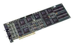 |
Each of the four channels on the IC-ASYNC can acquire images independently and asynchronously. Every channel has its own 1K x 1K linear frame buffer. Video input can be composite, variable scan, progressive scan, or VGA. Independent external trigger, frame reset, strobe, sync, timebase settings, AOI settings, and input conditioning circuitry is provided for each channel.
Each frame buffer acquires image data independently based on timing from its associated camera input channel. A de-interlacing feature allows consecutive fields to be merged during acquisition. Multiple frame modes allow up to 8 images to be consecutively acquired into the frame buffer. Ping-Pong bus master mode allows consecutive acquisition and transfer of images with no lost frames-guaranteed! A sub-sample mode allows for decimation of the incoming video data (x2, X and Y) for resizing images on-the-fly.
The IC-ASYNC incorporates a state-of-the-art bus master controller (BMC) that autonomously monitors images as they are being acquired into each of 4 frame buffers and transfers the image data to host memory (interrupt based). The host CPU is thus free to process data during bus master transfers rather than controlling each individual transfer operation. The BMC provides multiple frame ping-pong source and destination capabilities which enables continuous real-time processing of each image. The BMC uses a programmable scatter-gather table that eliminates the need for the host to monitor bus master transfers
Video Formats
- Supports independent asynchronous acquisitions from up to 4 cameras
- Supports non-standard area scan cameras up to 1K x 1K; variable scan
- Supports up to 2 dual-tap asynchronous camera inputs
Features & Benefits
- On-board 1MB frame buffer for each of the 4 channels. DMA bus master transfers
images to host memory is less than 4ms
- Non-destructive overlay using compatible SVGA adapters
- Hardware circuitry automatically de-interlaces images during acquisition
- Supports trigger, strobe, and frame reset for applications demanding highly
responsive asynchronous image capture
- Multiple frame ping-pong source and destination capabilities for simultaneous
acquisition and transfer of images to host memory
- On-board 16-bit digital I/O allows for easy connection to industrial I/O peripherals
Applications
- High speed consumer package inspection, can/bottle and pharmaceutical inspection
- Multiple independent production lines
- Multi-point integrated circuit device inspection
- High speed Tandem batch inspection

| Specifications |
Sensor Interface:
- Four independent analog video inputs, AC coupled & terminated to 75 Ohms
- Monochrome "standard" video camera and sources: RS-170, CCIR, VGA etc,. accepts composite video or driven with external timing (HSYNC, VSYNC, VRESET)
- 2 dual-tap asynchronous camera inputs
- Programmable Timebase Generator and pixel clock; programmable resolution to 1024 x 1024 interlaced or non-interlaced. Outputs horizontal, vertical and reset timing to camera
- Programmable PLL (Phase-Locked Loop)
Video Digitizer:
- 20 MHz Monotonic 8-bit flash ADC; Input pixel rates to 20 MHz
Video Memory:
- 4 independent 1MB frame buffers
On Board Digital I/O:
- 16 bits: 8 bits in; 8 bits out
- Input Latching
Video Signal Conditioning:
- Programmable gain adjust - positive ADC reference (full-scale) from 0 to +2 Volts in 64 steps
- Programmable offset - negative ADC reference (zero) software programmable from 0 to +1.2 Volts in 64 steps
- Look-Up-Table - 8 in - 8 out following ADC
- DC Restoration - programmable clamp pulse
- Input gain - software selectable: 1.0x or 1.5x
- Low-pass filter 6.0 Mhz fixed
External Trigger, Strobe Control, and Frame Reset:
- External Trigger input per camera; synchronizes acquisition to external events. Falling edge trigger - minimum input pulse width 50 nsec
- Frame Reset Mode: external trigger initiates camera frame reset, strobe, and image acquisition for immediate capture of moving objects
- Trigger on Frame Mode: strobing and image acquisition are synchronized with the video signal
- Strobe outputs per camera with programmable polarity; 120-msec nominal duration
- Programmable position of strobe relative to camera timing
- Programmable frame reset delay 1 to 511 lines (increments of one line)
- Acquire on next field
Video Window Generator:
- Allows selection of video window within video signal
- Horizontal offset programmable 0 to1023 pixels (one increments)
- Horizontal size programmable from 4 to 1024 pixels (increments of four)
- Vertical offset programmable 0 to 1023 lines (one increments)
- Vertical size programmable 1 to 1024 lines (one increments)
Interrupts:
- Host interrupt on occurrence of strobe, trigger, VB or acquisition
Hardware Color Dot Clipping:
- Image data can be "clipped" during bus master to a Windows display device to eliminate any conflicts with Windows reserved colors.
On Board Decimation:
- Image reduction on acquisition by factors of 2
Display - Windows:
- Provides Non-destructive Overlay
- A DirectX compatible SVGA adapter required for real-time display
Automatic Double Buffered Full Fram Acquisition:
- Hardware controlled "ping-pong" acquisition into image memory, provides most efficient acquisition and bus-master synchronization possible
Bus Requirements:
- 32 bit PCI slot
- 1.3 Amps @ +5 volts
- 0.2 Amps @ +12 volts
- Full slot PCI card
Power Output:
- 500 ma @ +12 volts/camera (2 Amp total)
- 500 ma @ +5 volts to digital I/O
|
If you like this page, please recommend it and share it. |
||
| More | ||