|
||||||||||||||||||||||||||||||||||||||||||
|
||||||||||||||||||||||||||||||||||||||||||

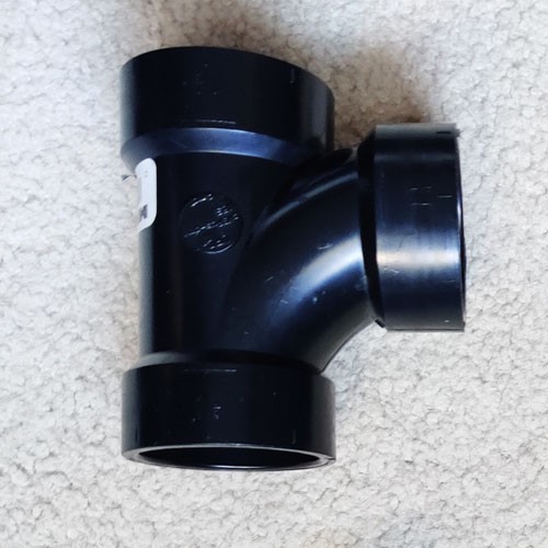
Gocator 360º 3D scanning provides measurements of all surfaces on a target object
Back
to Newsletter
Go
to LMI Technology
Go to 3D Cameras
| How to make measurements on surfaces of a 360º object | ||
|
Gocator software now supports 3D mesh data for advanced shape measurement and inspection of multi-view 360º surface scans. Mesh data consists of "stitched" scans from multiple sensors. Consequently, end users receive a 360º Mesh of the object that can be used for measurement with other surface tools.
Step 1: Perform high accuracy 6 DoF alignment With six-degrees of freedom alignment, system engineers can now generate high-accuracy 3D Mesh scans from ring multi-sensor layouts. To perform alignment, we first set up 4 sensors in a ring layout and scan an alignment target. Captured data from each sensor is displayed simultaneously.
With the addition of a Surface Align Ring tool users can calculate the transformations for the 4-sensor ring layout with 6 degrees of freedom. The results of this high accuracy alignment are saved in an XML file, and include compensations for X angle rotations. We then load the XML file in a Surface Mesh tool, which stitches the scan data from our 4-sensor ring layout into single mesh, or 360º scan.
Users scan the pipe fitting with the ring layout multi-sensor
system and apply the same aligned transformations to the data
that was established in the previous step. The result is a 360º
Mesh of the pipe fitting, aligned with 6 degrees of freedom.
Designers also have the ability to apply dedicated Mesh tools directly to raw Mesh data (e.g. for dimensional and deviation measurements), such as the Mesh Plane and Mesh Bounding Box tools.
Next users will apply measurements to our multiple features of interest. To do this, we apply the Surface Cylinder tool to the top surface of the pipe fitting, using separate instances for each radius we want to measure.
In order to measure the feature on the bottom of the pipe fitting, we add a Surface Circular Edge tool to determine the internal radius of the opening.
To determine the external radius of the opening,
we simply duplicate the tool and change the search direction to
inward to generate our measurement result. We can add other Surface
tools to the projected data in the same way, allowing for advanced
measurement on the sides of objects or any other perspective we
require. |


| Need a
price or more application information? Please
email Adept Turnkey or call our offices Adept Turnkey Pty Ltd is"The Machine Vision and Imaging Specialists" and distributor of LMI products in Australia and New Zealand. To find out more about any LMI product, please call Adept Turnkey at Perth (08) 9242 5411 / Sydney (02) 9905 5551 / Melbourne (03) 9384 1775 or contact us online. |
|
If you like this page, please recommend and share it. |
||
| More | ||